PCB vs PCBA: Types, Differences, and Applications Explained
 19 Jun 2025 11:23:17 GMT
PCBASAIL
Did you ever stop to think that almost every gadget or electronic device you use in your daily life has one thing in common at its core? Seriously—your PC, laptop, smartphone, game console, microwave, TV, dishwasher—even your smart home hub—none of these would work without a PCB assembly. So, what exactly is PCB assembly?
What “PCB Assembly” Means
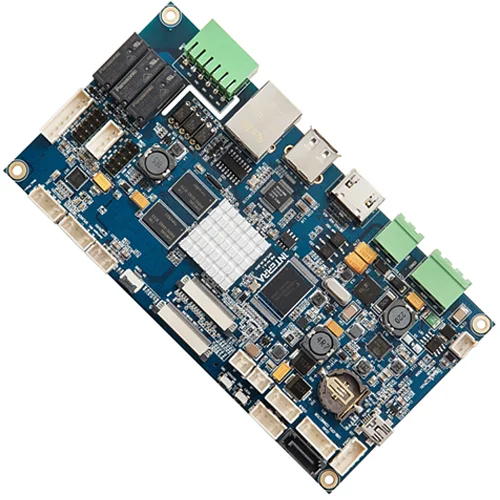
PCB assembly (often called PCBA) is basically the process of soldering and mounting electronic components onto a bare printed circuit board (PCB). First, you manufacture or procure the blank circuit board. Then, you use specialized production equipment—think pick‑and‑place machines, reflow ovens, wave solder machines—to populate that board with resistors, capacitors, ICs, connectors, and whatever else the design calls for. Once everything’s soldered on and tested, you’ve got a PCBA—a fully functional circuit board ready to go into your device.

PCB vs. PCBA: What’s the Difference?
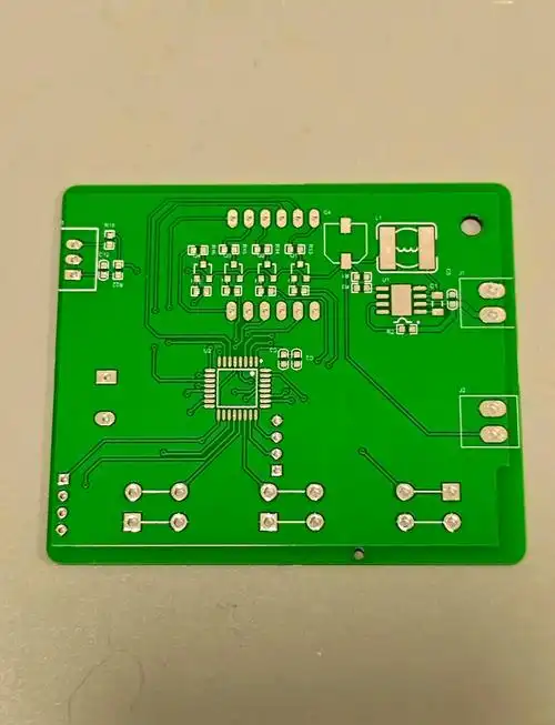
PCB: This is the “bare” printed circuit board. Picture a flat, green (or sometimes blue, black, red) board with copper traces etched into it, holes drilled out, and no components attached. On its own, it can’t do much—it’s just a structured piece of insulating material (usually epoxy and fiberglass) with a layer (or layers) of copper.

PCBA: Short for “printed circuit board assembly.” Once you’ve soldered on all the electronic parts and run any necessary quality checks, that bare PCB transforms into a PCBA. It’s the PCBA that actually goes into your device and makes it work; the bare PCB is just the foundation.
The PCB Assembly Process
Putting together a PCBA isn’t just “pop on parts and hit it with a soldering iron.” It’s a multi‑step, sometimes non‑linear process that can change based on factors like volume, cost targets, complexity, and the intended application. Here are the main ingredients you need before you even start:
The bare PCB itself, often called the substrate or board.
Electronic components, chosen to meet the functional and performance needs of the device. A simple radio might have a handful; a modern smartphone PCBA could have hundreds, sometimes spread across multiple layers. Some high‑end motherboards even sport a dozen or more copper layers!
Solder materials—this includes solder wire, solder paste, pre‑form bars, and so on, depending on whether you’re doing wave, reflow, or hand soldering.
Flux, to help the solder flow properly and ensure reliable joints.
Assembly equipment: pick‑and‑place machines, wave solder machines, reflow ovens (IR, convection, vapor phase), inspection gear (automated optical inspection, X‑ray), test fixtures, and sometimes selective soldering systems.
Once you have all that lined up, you can dive into the assembly. But before that, let’s dig in a bit on the PCB itself.
Three Main Types of PCBs
A PCB is essentially a sandwich of insulating material (like epoxy‑glass) and conductive copper layers, etched to form the interconnecting traces. The number of layers and the flexibility of the board vary widely by application. Here are the big four to know:
Single‑Sided PCB
Just one copper layer on an insulating substrate.
Cheap and simple, perfect for low‑cost and low‑complexity applications (think basic calculators, hobby kits).
Double‑Sided PCB
Copper layers on both sides of the board, connected by plated through‑holes.
Gives you more routing options than single‑sided, but still pretty straightforward and cost‑effective.
Multilayer PCB
Multiple alternating layers of copper and insulating material, sometimes up to 12 layers (or more in specialized designs).
Ideal when you need high‑density routing in a compact space—modern smartphones, computer motherboards, servers, medical devices, and more.
Rigid PCB
Uses a solid, stiff substrate (like FR‑4 glass‑epoxy).
Cannot be bent, offers strong mechanical support—think desktop PC motherboards, power supplies, industrial controllers.
Flexible PCB (Flex PCB)
Made with bendable plastic substrates (like polyimide).
Lets you fold and twist the board to fit odd shapes—common in wearable devices, foldable phones, and tight spaces in automotive or aerospace gear.
Metal Core PCB (MCPCB)
Has a metal (usually aluminum or copper) base for heat dissipation, topped with insulating and copper layers.
Great for high‑power or high‑heat applications: LED modules, power converters, automotive lighting.
Common Assembly Methods
Depending on cost, volume, part types, and performance requirements, factories choose between a few main mounting techniques:
Surface Mount Technology (SMT)
How it works: Tiny surface‑mount devices (SMDs) are placed directly onto pads on the PCB surface, then run through a reflow oven to solder them in place.
Why we love it: High component density, super fast production, great for automated lines.
Where it’s used: Almost every modern consumer electronics board from phones to TVs to laptops.
Through‑Hole Technology (THT)
How it works: Leads on components go through drilled holes and are soldered on the opposite side—either by wave soldering or by hand/robotic insertion and soldering.
Why it sticks around: Better mechanical strength, ideal for connectors, large heat sinks, and components like electrolytic capacitors or inductors.
Where you see it: Power supplies, industrial equipment, older designs, or any board where you need more rugged connections.
Selective Soldering
How it works: A wave of molten solder contacts only selected areas (like through‑hole pins), avoiding surface‑mount parts.
Why it’s handy: Combines SMT and THT processes without damaging sensitive SMDs during wave soldering.
Hand Soldering / Rework
How it works: Technicians use soldering irons or hot‑air stations to attach or fix parts.
Why it’s needed: Prototyping, rework, or very low‑volume runs where setting up automated lines isn’t economical.
Typical Applications for Each Method
SMT: Ubiquitous in consumer electronics—smartphones, laptops, gaming consoles, TVs, even your dishwasher’s control panel.
THT: Power supplies, heavy connectors, large capacitors (older technology still prevalent in industrial and military gear).
Selective Soldering: Mixed‑technology boards where you’ve got both SMT chips and some through‑hole parts.
Flex PCBs: Wearables, medical devices, connectors in printers, or inside tight automotive modules.
MCPCBs: LED lighting arrays, high‑power modules, automotive headlamps, and anything where heat needs to get out fast.
Wrapping It All Up
PCBs are absolutely everywhere in modern life, yet we rarely give them a second thought. Over the decades, the ways we mount parts—going from point‑to‑point wiring to through‑hole to today’s high‑speed SMT—have evolved enormously. Each method and board type has its own sweet spot: sometimes you need the rigidity of a glass‑epoxy board; other times you crave the flexibility of a polyimide flex board. Whether it’s a simple single‑layer hobby board or a 12‑layer rigid‑flex masterpiece inside the latest smartphone, PCB assembly is the unsung hero powering our tech‑driven world.
| PCB Type | Summary |
|---|---|
| Single-Sided PCB | Used in simple systems, low-cost, common among hobbyists |
| Double-Sided PCB | Less common than multilayer, uses both sides of the board |
| Multilayer PCB | Mass-produced, cost-effective, compact; up to 10 or 12 layers |
| Rigid PCB | Stronger substrate, used in high-impact applications, military, aerospace |
| Flexible PCB | For moving parts, more expensive, longer lifespan |
| Metal Core PCB | Metal base (e.g., copper), for specialized use like conductivity or heat dissipation |


