Table of Contents
PCBs (Printed Circuit Boards) are classified by flexibility into three types: rigid circuit boards, flexible circuit boards, and rigid - flex boards. The intuitive difference between rigid PCBs and flexible PCBs is that flexible PCBs can be bent. Common thicknesses of rigid PCBs include 0.2mm, 0.4mm, 0.6mm, 0.8mm, 1.0mm, 1.2mm, 1.6mm, 2.0mm, etc. Flexible PCBs typically have a thickness of 0.2mm, with reinforced layers of 0.2mm or 0.4mm added behind areas where components need to be soldered. Understanding these specifications helps structural engineers reference spatial dimensions during design. Common materials for rigid PCBs include phenolic paper laminates, epoxy paper laminates, polyester glass mat laminates, and epoxy glass cloth laminates. For flexible PCBs, common materials include polyester film, polyimide film, and fluorinated ethylene propylene (FEP) film.

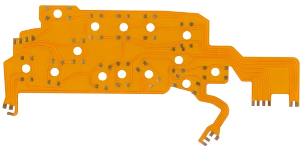
An FPC (Flexible Printed Circuit) board, also known as a flexible circuit board, is a highly reliable and flexible printed circuit board made from polyimide or polyester film as the base material. It features high wiring density, lightweight, thin thickness, and excellent bendability, primarily used for connecting with other circuit boards. FPC flexible boards can save internal space in electronic products to a certain extent, making product assembly and processing more flexible. For example, in smartphones, LCD/OLED and AMOLED display panels are connected via FPC flexible boards. They are also widely used in laptops, digital cameras, as well as medical, automotive, and aerospace fields.
Flexibility and Reliability of Flexible Circuits
Currently, FPCs are categorized into four types: single - sided, double - sided, multi - layer flexible boards, and rigid - flex boards.
Single - sided flexible boards are the lowest in cost and suitable for printed boards with low electrical performance requirements. They should be chosen for single - sided wiring. They have a single layer of chemically etched conductive patterns, with the conductive layer on the flexible insulating substrate being rolled copper foil. Insulating substrates can be polyimide, polyethylene terephthalate (PET), aramid fiber ester, or polyvinyl chloride (PVC).
Double - sided flexible boards have a layer of etched conductive patterns on both sides of the insulating base film. Metallized vias connect the patterns on both sides of the insulating material to form conductive pathways, meeting the design and functional requirements for flexibility. Coverlays protect the single or double - sided conductors and indicate component placement positions.
Multi - layer flexible boards are formed by laminating three or more layers of single - sided or double - sided flexible circuits, with metallized vias created through drilling and electroplating to establish conductive pathways between layers. This eliminates the need for complex soldering processes. Multi - layer circuits offer significant functional advantages in terms of higher reliability, better thermal conductivity, and easier assembly. When designing the layout, the interplay between assembly dimensions, number of layers, and flexibility must be considered.
Traditional rigid - flex boards are composed of selectively laminated rigid and flexible substrates, with a compact structure and conductive connections via metallized vias. They are an excellent choice if components are placed on both sides of the printed board. However, if all components are on one side, using a double - sided flexible board with an FR4 reinforcing layer laminated on the back is more cost - effective.
Hybrid - structure flexible circuits are multi - layer boards with conductive layers made of different metals. For example, an 8 - layer board might use FR - 4 as the inner - layer dielectric and polyimide as the outer - layer dielectric, with leads extending in three different directions from the main board, each made of a different metal (e.g., constantan alloy, copper, and gold as independent leads). This hybrid structure is often the only viable solution for applications requiring electrical signal conversion, heat transfer, or stringent electrical performance under low - temperature conditions. It can be evaluated based on the convenience of interconnection design and overall cost to achieve the best performance - cost ratio.
Disadvantages and Advantages of FPC Flexible Printed Circuit Boards
Disadvantages of FPCs:
High initial one - time cost
Flexible PCBs are designed and manufactured for specific applications, resulting in high upfront costs for circuit design, wiring, and photomask preparation. Unless specifically required, they are generally not recommended for low - volume applications.
Difficulty in modification and repair
Once fabricated, modifying a flexible PCB requires starting from the base map or reprogramming the photoplotting process, making changes cumbersome. The surface is covered with a protective film that must be removed before repair and reapplied afterward, complicating the repair process.
Size limitations
Currently, flexible PCBs are often manufactured using intermittent processes, limited by the size of production equipment, making it difficult to produce very long or wide boards.
Susceptibility to damage from improper handling
Improper operation by assembly personnel can easily damage flexible circuits. Soldering and rework require trained personnel.
Advantages of FPCs:
A flexible printed circuit board (FPC), made from a flexible insulating substrate, offers numerous advantages over rigid printed circuit boards:
Free bending, rolling, and folding
It can be arbitrarily arranged according to spatial layout requirements and can move and stretch in three - dimensional space, achieving integration of component assembly and wire connections.
Significant reduction in size and weight
FPCs help greatly minimize the volume and weight of electronic products, meeting the needs of high - density, miniaturization, and high - reliability development. Therefore, they are widely used in aerospace, military, mobile communications, laptops, computer peripherals, PDAs, digital cameras, and other fields.
Additional benefits
FPCs also feature good heat dissipation, solderability, easy assembly, and lower overall costs. The rigid - flex design partially compensates for the slightly lower component - carrying capacity of flexible substrates.
 19 May 2025 15:29:09 GMT
PCBASAIL


