What is a Rigid PCB?
Both rigid and flexible printed circuit boards (PCBs) are used to connect electronic components in various consumer and non-consumer devices. As the name suggests, a rigid PCB is a circuit board built on a rigid base layer that cannot be bent, while a flexible PCB (also known as a flexible circuit) is constructed on a flexible base that can be bent, twisted, and folded.
Rigid PCBs, often simply referred to as PCBs, are what most people envision when they think of a circuit board. These boards connect electrical components using conductive tracks and other elements arranged on a non-conductive substrate. In rigid circuit boards, the non-conductive substrate typically contains glass, which reinforces the board and gives it strength and rigidity. Rigid circuit boards provide good support for components and offer excellent thermal resistance.
Differences Between Flexible FPC and Rigid PCB
Flexible FPC
Flexible PCBs use flexible base materials such as polyimide (PI). The flexible base allows flexible circuits to withstand vibration, dissipate heat, and be folded into various shapes.
Due to their structural advantages, flexible circuits are increasingly chosen for compact devices such as smart wearables, mobile phones, and cameras.
Rigid PCB
Rigid PCBs are built on a rigid base layer that cannot be bent. The non-conductive substrate typically contains glass, which reinforces the board and gives it strength and rigidity.
Rigid circuit boards provide good support for components and offer excellent thermal resistance, making them suitable for a wide range of electronic devices.
In recent years, driven by the rapid growth of the consumer electronics market, led by mobile electronic devices such as smartphones and tablets, the trend toward smaller and thinner devices has become increasingly evident. Consequently, traditional PCBs can no longer meet product requirements. As a result, major manufacturers have begun researching new technologies to replace PCBs, and among these, FPC, as the most favored technology, is becoming a primary connecting component in electronic devices.
Additionally, driven by emerging markets such as 5G and wearable devices, FPC will also usher in new growth opportunities.
Key Characteristics Comparison
Materials
- FPC: Flexible polyimide (PI)
- Rigid PCB: Epoxy resin and glass fiber woven cloth composite
Solder Mask
- FPC: Cover coating (thin polyimide)
- Rigid PCB: Solder mask layer on both sides
Manufacturing
- FPC: Requires special tools for handling
- Similar steps, but FPC uses cover film
Cost
- FPC: More expensive initially
- Rigid PCB: Lower initial cost
- FPC offers long-term cost benefits
Applications of FPC
Mobile Phones
Emphasize the light weight and thin thickness of flexible circuits, which can effectively save product volume and easily integrate connections.
Computers & LCD Screens
Utilize the integrated circuit configuration and thin thickness of flexible circuits to convert digital signals into images.
CD Players
Leverage the three-dimensional assembly characteristics and thin thickness of flexible circuits to transform large CDs into portable companions.
Disk Drives
Both hard disks and floppy disks rely heavily on the high flexibility and ultra-thin thickness of FPC to quickly read data.
Bluetooth Headsets
Small devices benefit from FPC's compact design and flexibility, allowing for innovative product shapes and improved user experience.
VR Glasses & Smartwatches
Latest applications in wearable technology utilize FPC's flexibility and space-saving properties for comfortable, functional designs.
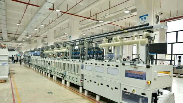
Our PCB Factory Capabilities
Our PCB factory specializes in the production of single and double-sided, multi-layer high-precision printed circuit boards, with over ten years of experience in PCB design, prototyping, and manufacturing.
Factory Scale
16000m² area
2000m²/month output
3000+ PCB categories
PCB Range
Up to 32 layers
HDI(3+n+3)
Heavy copper, high-frequency, aluminum-base
Service Advantages
24-hour express service
Free sample support
10+ years experience
Quality Standards
IPC-Class2 Standard
IPC-Class3 Standard
Multi-industry certification
Served Industries
PCB Manufacturing Process
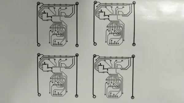
Printing the Circuit Board
Print the designed circuit board onto transfer paper. Note that the glossy side should face you. Usually, print two circuit boards on one sheet, and use the best-printed one for production.
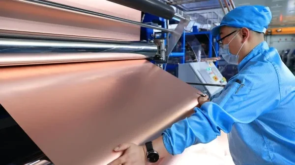
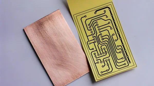
Cutting the Copper-Clad Laminate
A copper-clad laminate is a circuit board with copper foil on both sides. Cut the copper-clad laminate and use a photoresist board to create a full-size circuit board layout.
Preprocessing & Transferring
The oxide layer on the surface of the copper-clad laminate needs to be sanded with fine sandpaper to ensure proper adhesion.
Transfer the printed circuit board to the copper-clad laminate using a thermal transfer machine, ensuring proper alignment.
Etching the Circuit Board
Check if the circuit board transfer is complete. If some areas are incomplete, repair them with a black oil-based marker before etching.
Etching solution: Concentrated hydrochloric acid : concentrated hydrogen peroxide : water = 1:2:3. Always prioritize safety during operation!
Drilling, Preprocessing & Soldering
Drill holes for electronic components, then preprocess the board by sanding off the toner and applying rosin.
Solder all electronic components onto the circuit board and power it on. Before manufacturing, use DFM analysis to check for design defects.
PCB Substrate Materials
Substrate materials are divided into rigid substrates and flexible substrates. Rigid printed circuit boards use various materials depending on their application requirements.
3.1 Copper-Clad Epoxy Glass Cloth Laminates
It is a laminate substrate with epoxy resin as the adhesive and glass fiber cloth as the reinforcing material. Its mechanical properties, dimensional stability, and impact resistance are better than those of paper-based laminates.
The ε values of FR4 and FR5 range from 4.3 to 4.9. They have excellent electrical performance, allow for higher operating temperatures (130°C for FR4 and 170°C for FR5), and are less affected by environmental humidity, making them widely used in electronic communication equipment.
3.2 Epoxy Glass Cloth Prepregs for Multilayer Boards
It is a glass cloth material pre-impregnated with B-stage epoxy resin. When producing multilayer boards, it serves as the bonding material to laminate and bond separate single-layer printed circuit boards with conductive patterns. After lamination, it acts as a dielectric insulation layer.
3.3 Self-Extinguishing Copper-Clad Laminates
In addition to having the corresponding properties of the aforementioned copper-clad laminates, this material is flame-retardant, providing a certain resistance to fire hazards and small flame spread caused by overheating of individual electronic components.
3.4 Copper-Clad PTFE Glass Fiber Boards
These boards use polytetrafluoroethylene as the adhesive and glass fiber as the reinforcing material. They have excellent dielectric properties, high-temperature resistance, moisture resistance, and good chemical stability.
3.5 Copper-Clad Metal-Based PCBs
Also known as metal-core printed circuit boards, they use metal plates (usually aluminum) instead of reinforcing materials. They offer good heat dissipation, excellent dimensional stability, and shielding properties.
3.6 Flexible Printed Circuit Substrates
Flexible substrates are made by bonding copper foil to a thin plastic base sheet, including:
- Polyester film
- Polyimide film
- Fluorinated ethylene propylene (FEP) film
Need Rigid PCB Manufacturing Services?
We provide high-quality rigid PCB manufacturing and assembly services for various industries. Contact us today for a quote!
Get a Quote