Rigid-Flex PCBs
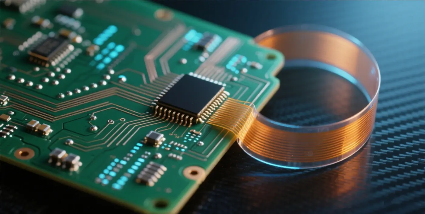
Rigid-Flex PCBs, which combine Flexible Printed Circuits (FPC) and Printed Circuit Boards (PCB), are formed by bonding these two through processes like lamination during PCB prototyping, following relevant technical specifications. This results in a circuit board that possesses the characteristics of both FPC and PCB. A typical rigid-flex PCB features two sets of rigid covers on its upper and lower surfaces, with one or more layers of FPC sandwiched in between. Generally, the cover areas of rigid-flex PCBs remain free of circuits. The covers and FPC are firmly attached and extend to the rigid regions, i.e., the parts containing PTH (Plated Through Holes). In areas requiring flexibility, the flexible layers may either be attached to each other or separated, depending on the required flexural strength or manufacturing costs.
Advantages of Rigid-Flex PCBs
One of the key features of rigid-flex PCBs is their slim profile and versatile shape, making them ideal for ultra-thin and lightweight packaging. While they may be more expensive in terms of design and manufacturing, they offer numerous advantages that address many limitations of traditional rigid board technologies.
Compact Size & Flexible Form
Rigid-flex PCBs make it easier to fit more components in smaller spaces as they can be shaped according to specific contours. This technology reduces the size, weight, and overall system cost of the final product. Additionally, their compact design makes them an excellent choice for fine-line and high-density circuits in HDI (High-Density Interconnect) technology.
Customizable for Diverse Applications
Rigid-flex PCBs offer flexible packaging geometries, allowing customization for applications across industries such as aerospace, military, medical devices, and consumer electronics. They can be tailored in size and shape to fit enclosure designs and 3D configurations, providing designers with greater flexibility to meet specific application requirements.
Enhanced Mechanical Stability
The stability of rigid boards combined with the flexibility of flexible sheets creates a stable overall packaging structure, while maintaining the reliability of electrical connections and flexibility needed for installation in small spaces.
Superior Performance in Harsh Environments
Rigid-flex PCBs boast high impact and vibration resistance, enabling them to function normally in high-stress environments. They also use fewer cables and connectors, reducing safety risks and maintenance needs during future use.
Ease of Manufacturing and Testing
Rigid-flex PCBs require fewer interconnects and related components/parts, simplifying assembly operations and making them easier to assemble and test. They are highly suitable for PCB prototyping.
Additional Performance Benefits
Beyond the above advantages, rigid-flex PCBs also offer benefits such as high circuit density, excellent heat dissipation, and chemical resistance. In summary, they combine all the strengths of rigid and flexible boards while compensating for their weaknesses. This type of PCB is the optimal solution for designing reliable and robust circuits in smart wearables and other industries.
Applications of Rigid-Flex PCBs
Industrial Use
This includes rigid-flex boards for industrial, military, and medical applications. Most industrial components demand precision, safety, and durability. Therefore, the required characteristics of rigid-flex boards are: high reliability, high precision, low impedance loss, stable signal transmission quality, and durability.
However, due to the high complexity of the manufacturing process, production volumes are small and unit prices are relatively high.
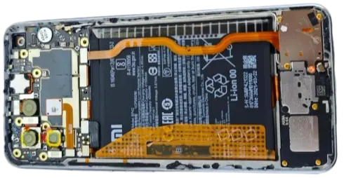
Mobile Phones
In mobile phone applications, rigid-flex boards are commonly used in areas such as the hinge areas of foldable phones, camera modules, keyboards, and RF modules.
Consumer Electronics
In consumer products, DSC (Digital Still Cameras) and DV (Digital Video Cameras) are representative of the development of rigid-flex boards, with a focus on two main aspects: performance and structure. In terms of performance, rigid-flex boards enable 3D connections between different rigid PCBs and components. Thus, with the same line density, the total usable area of the PCB can be increased, relatively enhancing its circuit-carrying capacity and reducing signal transmission limitations at contact points and assembly errors. On the structural front, the thin and lightweight nature of rigid-flex boards, along with their ability to be bent for wiring, greatly helps reduce volume and weight.
Automotive
In automotive applications, rigid-flex boards are typically used to connect buttons on the steering wheel to the main board, link the vehicle's video system screen to the control panel, connect the operation of audio or function keys on side doors, connect sensors in reverse radar imaging systems (including those for air quality, temperature and humidity, and special gas regulation), vehicle communication systems, satellite navigation, rear-seat control panels to front-end controllers, and external vehicle detection systems.
Medical Devices
Included in industrial use, medical devices require rigid-flex boards that offer precision, safety, and durability. They are ideal for medical devices requiring compact design, reliability in harsh environments, and flexible form factors to fit specialized equipment.
When to Use Rigid-Flex PCBs
-
High-impact and high-vibration environments
Rigid-flex PCBs offer strong impact resistance and can be used in high-stress environments to ensure stable device performance, preventing potential equipment failures.
-
High-precision applications where reliability takes precedence over cost
If cable or connector failures could pose risks, more durable rigid-flex boards are the better choice.
-
High-density applications
When components lack sufficient surface area to accommodate all necessary connectors and cables, rigid-flex boards can save space to address this issue.
-
Applications requiring multiple rigid boards
When an assembly contains four or more interconnected boards, replacing them with a single rigid-flex board may be the optimal and more cost-effective solution.
Design Requirements for Rigid-Flex PCBs
Layout Requirements
- Components are placed in the rigid areas, with the flexible areas used solely for connection purposes. This ensures a longer bending life and improved reliability. Placing components in flexible areas may lead to pad cracking, damage, or character peeling.
- When components are placed in rigid areas, the distance from the component edge to the rigid-flex junction should be greater than 1mm.
- If the flexible area extends into the rigid area, the distance between them should be at least 1mm.
-
Wiring Requirements
- The routing direction of traces in flexible areas should be perpendicular to the bending line. Traces at bending points can use arc connections to prevent pattern cracking in one direction during bending tests.
- The distance from patterns in flexible areas to the board edge should be at least 10mil, and no holes should be drilled here. The distance from vias to the rigid-flex junction should be at least 2mm.
- If the flexible area has inner layers, isolation can be added in the flexible area (without affecting power connectivity, current values, or impedance) to enhance flexibility.
- To facilitate differentiation during production, flexible area markers should be added to the mechanical auxiliary layers for the flexible sections.
- If impedance design is required and impedance traces need to be routed in the flexible area, it is essential to ensure that each routing layer in the flexible area has a corresponding reference layer on each individual board when developing the impedance structure diagram.
Production Differences Between Flexible PCBs and Rigid-Flex PCBs
The basic SMT (Surface Mount Technology) assembly process is similar for flexible PCBs, rigid-flex PCBs, and rigid PCBs, as all require component mounting and solder paste welding through reflow soldering. However, flexible and rigid-flex PCBs have unique characteristics; failure to adhere to these additional requirements during production can cause significant issues.
Solder Paste Printing Process
Like rigid PCB processing, solder paste is applied to flexible and rigid-flex PCBs using stencils and solder paste printers. Many SMT operators face challenges with size and fragility. Unlike rigid boards, flexible PCBs have uneven surfaces, requiring fixtures and positioning holes for stabilization. Additionally, flexible circuit materials are dimensionally unstable, expanding or contracting by 0.001 inches per inch with changes in temperature and humidity. Interestingly, these expansions and contractions can cause shifts in the X and Y directions of the board. As a result, flexible mounting often requires smaller carriers compared to rigid PCB SMT.
SMT Component Mounting
With the trend toward miniaturization of SMT components, smaller components can cause issues during reflow soldering. If the flexible circuit is small, expansion and contraction are less significant, potentially requiring smaller SMT carriers or additional Mark points. Poor overall flatness of the carrier can also lead to component shifting during mounting. SMT fixtures are crucial for maintaining the flatness of the mounting surface.
Reflow Soldering Process
A key difference between flexible/rigid-flex PCBs and rigid PCBs in component mounting is that flexible circuits must be dried before reflow soldering. In addition to dimensional instability, flexible materials are hygroscopic, absorbing moisture like a sponge (up to 3% weight gain). Once a flexible circuit absorbs moisture, reflow soldering must be halted. While rigid PCBs face similar issues, they have higher tolerance. Flexible circuits require preheating baking at ~225° to 250°F, which must be completed within 1 hour. If not baked promptly, they should be stored in dry cabinets or nitrogen storage rooms.
Need Rigid-Flex PCB Solutions?
We provide custom rigid-flex PCB manufacturing services tailored to your specific application requirements. Contact us for expert support.
Request a Quote