What is an Aluminum PCB?
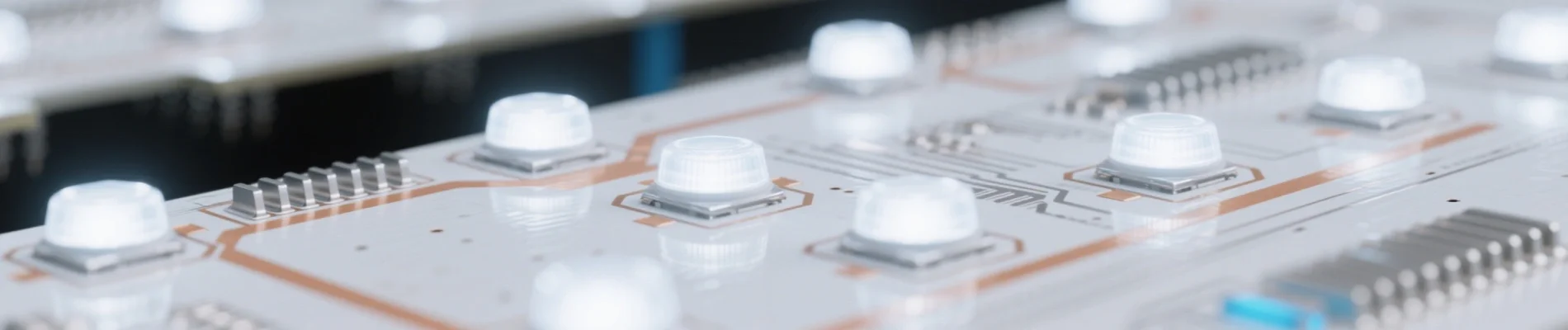
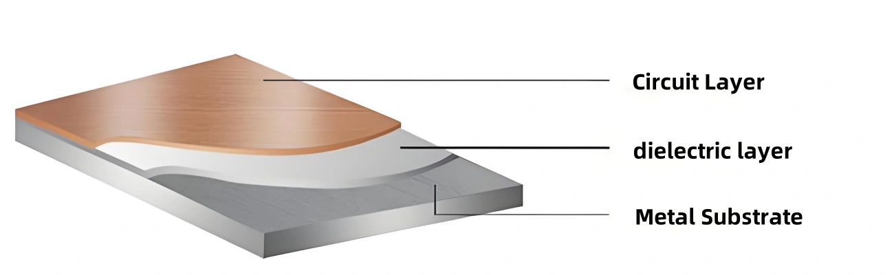
An Aluminum PCB is a metal-based copper-clad laminate with excellent heat-dissipating performance. Typically, a single-sided board consists of three layers: a circuit layer (copper foil), a dielectric layer, and a metal substrate layer. It is commonly used in LED lighting applications. It has two sides: the white side is for soldering LED pins, while the other side—showing the natural aluminum color—is usually coated with thermal conductive paste to make contact with heat-dissipating components (e.g., heat sinks). Currently, there are also ceramic substrates, among other alternatives.
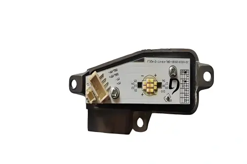
An LED Aluminum PCB is a type of printed circuit board (PCB) that uses aluminum alloy as the base material instead of traditional fiberglass-reinforced substrates (e.g., FR-4). Since LEDs generate significant heat, LED fixtures typically utilize Aluminum PCBs for faster heat conduction, whereas PCBs in other devices or appliances still rely on fiberglass-based boards.
Structure of Aluminum PCBs
1. Circuit Layer
The circuit layer (usually electrolytic copper foil) is etched to form printed circuits, enabling component assembly and connections. Compared to traditional FR-4, an Aluminum PCB with the same thickness and line width can carry higher currents.
2. Dielectric Layer
The dielectric layer is the core technology of Aluminum PCBs, primarily responsible for bonding, insulation, and heat conduction. It acts as the largest thermal conduction barrier in power module structures. The better the thermal conductivity of the dielectric layer, the more efficiently heat generated by components during operation can dissipate, which helps reduce component operating temperatures, thereby increasing power load capacity, reducing size, extending lifespan, and improving power output.
3. Metal Substrate Layer
The choice of metal for the insulated metal substrate depends on a comprehensive consideration of factors such as thermal expansion coefficient, thermal conductivity, strength, hardness, weight, surface condition, and cost.
In most cases, aluminum is the ideal choice due to its cost-effectiveness and technical performance. Common aluminum grades include 6061, 5052, and 1060. For higher thermal conductivity, mechanical performance, electrical properties, or other special requirements, copper, stainless steel, iron, or silicon steel plates may also be used.
Aluminum vs Copper Substrates
Aluminum PCBs
Most Aluminum PCBs are single-sided and fall under the category of metal-based PCBs. They are recognized for their excellent heat dissipation and are widely regarded as specialized PCBs in the LED industry.
Typically, an Aluminum PCB has two sides: the white side is for soldering LEDs, while the aluminum-colored side—often coated with thermal conductive paste to facilitate heat transfer—is in contact with heat-dissipating components. Structurally, it consists of three layers: a circuit layer, a dielectric layer, and a metal substrate layer.
High-end versions may be double-sided (circuit layer + dielectric layer + aluminum substrate + dielectric layer + circuit layer), while multi-layer Aluminum PCBs are rare. They are usually formed by bonding conventional multi-layer boards to an aluminum substrate via a dielectric layer.
Aluminum PCBs are widely used in hybrid integrated circuits, automotive electronics, power equipment, among other fields, thanks to their excellent heat dissipation, good machinability, dimensional stability, and reliable electrical performance.
Copper Substrates
Copper substrates, unlike general PCBs, are a type of metal-based substrate available in single-sided, double-sided, and multi-layer designs.
Key Advantages:
- Superior heat dissipation compared to aluminum
- Suitable for extreme temperature fluctuations
- Compatible with high-frequency circuit applications
They are primarily used in high-frequency circuits, environments with extreme temperature fluctuations, heat dissipation in precision communication devices, and architectural lighting applications.
Key Identification Tip: Aluminum PCBs cannot have vias. This makes it easy to identify an Aluminum PCB from a finished PCB—simply check for the absence of vias.
Design of Aluminum PCBs
Dimensional Requirements
Panel size and tolerance
Strictly control length and width within specified range to ensure assembly accuracy
Thickness and tolerance
Ensure material thickness uniformity meets design requirements
Perpendicularity
Ensure vertical accuracy of adjacent surfaces
Warpage
Control material flatness to avoid assembly issues
Appearance Requirements
Performance Requirements
Special Testing Methods
Circuit Fabrication of Aluminum PCBs
1 Machining
Aluminum PCBs can be drilled, but no burrs are allowed on or around the holes after drilling, as this will affect the voltage withstand test. Milling the outline is highly challenging. Punching the outline requires high-quality molds, and mold fabrication requires specialized techniques—this is one of the key challenges in aluminum PCB manufacturing. After punching, the edges must be neat, free of burrs, and must not damage the solder mask on the board edges. Typically, a combination mold is used: holes are punched from the circuit side, and the outline from the aluminum substrate side. Techniques such as applying upward shear force and downward pulling force during punching are employed. After punching, the board warpage should not exceed 0.5%.
2 Surface Protection
The aluminum substrate surface must not be scratched during production: Touching the aluminum substrate surface with bare hands or exposing it to certain chemicals can cause discoloration or blackening, which is unacceptable. Some customers may even reject re-polished aluminum surfaces. Thus, preventing scratches or contamination of the aluminum substrate surface throughout the process is a key challenge in aluminum PCB production. Common practices include using protective films before and after hot air solder leveling (HASL).
3 High-voltage Testing
Aluminum PCBs for communication power supplies require 100% high-voltage testing. Some customers specify DC voltage, others AC, with test parameters including 1500V or 1600V and durations of 5 or 10 seconds—100% of boards must undergo this testing.
Contaminants on the board, burrs around holes or at the aluminum substrate edges, jagged circuit traces, or any damage to the dielectric layer can lead to electrical leakage, dielectric breakdown, or even fire during testing. Boards exhibiting delamination or blistering after the test are rejected.
Production Specifications
Copper Foil Requirements
Aluminum PCBs are often used in power devices with high power density, thus requiring thicker copper foil. For copper foil thicker than 3oz, engineering designs must include line width compensation during etching; otherwise, the etched line width will fall outside tolerance ranges.
Surface Protection
The aluminum substrate surface must be protected with a protective film during PCB processing to prevent chemical corrosion, which would damage its appearance. Since the protective film is easily scratched—potentially requiring rework—racks must be used throughout the process to avoid contact with the aluminum substrate surface. This is another key challenge in production.
Milling Requirements
Milling tools for fiberglass PCBs have lower hardness, while those for Aluminum PCBs are significantly harder. The milling speed for fiberglass PCBs is much higher; milling for Aluminum PCBs is at least two-thirds slower.
Cooling Requirements
Fiberglass PCBs only require the machine’s built-in cooling system during CNC milling, whereas Aluminum PCBs require additional alcohol-based cooling for the milling head.
Application Fields
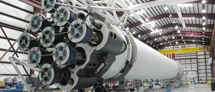
Aerospace
With lightweight characteristics (with a density one-third that of traditional PCBs) and superior heat dissipation (thermal conductivity over 10 times higher than that of FR-4), Aluminum PCBs are widely used in circuit modules for satellites and drones. For example, in drive circuits for satellite solar panels, replacing traditional PCBs with Aluminum PCBs reduces the weight of a single board by 20g, thereby cutting the total satellite weight by up to 4kg and significantly lowering launch costs.
Electronic Equipment
Aluminum PCBs are suitable for high-frequency circuits and power amplifiers, such as high-frequency amplifiers and filters in communication devices, as well as CPU boards and power units in computers. Their metal substrate structure effectively dissipates heat generated by high-frequency signal transmission and power conversion.
Automotive Electronics
They are used in components like engine control modules and headlight circuits, ensuring circuit stability in high-temperature (80°C–120°C) and vibrating environments. For instance, high-brightness LED headlights in premium vehicles rely on Aluminum PCBs to operate reliably under complex working conditions.
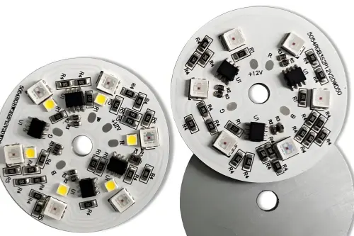
LED Lighting
Aluminum PCBs rapidly dissipate heat from LEDs (with a thermal conductivity of 20–50 W/m·K), keeping chip temperatures within a safe range (60°C–80°C), extending fixture service life, and enhancing luminous efficiency. They are widely used in high-power LED streetlights (100 W–300 W).
Industrial Control
Aluminum PCBs are applied in control cabinets and switching power modules within automated production lines, where they handle high power densities (5 W/cm²–10 W/cm²) and ensure a stable power supply. For example, in the power modules of industrial control equipment, Aluminum PCBs are used to sustain long-term high-load operation.
Need Technical Support?
Our team of PCB experts can provide detailed guidance on Aluminum PCB selection, design, and manufacturing processes tailored to your specific application requirements.