
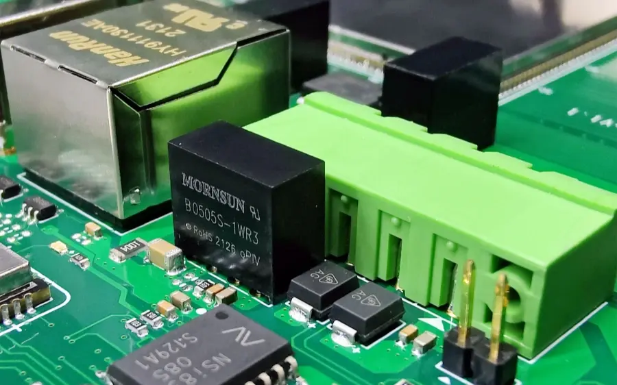
Surface Mount Technology (SMT) and Through-Hole Technology (THT) are two main ways to place and solder components on a printed circuit board (PCB). SMT and THT are used in final product assembly. SMT places small, flat, or surface-mount parts on the board surface. Then the parts are soldered by reflow soldering or other soldering methods. THT uses parts with leads that go through holes in the board. Those leads are soldered on the opposite side, usually by wave soldering or hand soldering. So, what is the real difference between SMT and THT on a PCB?
SMT is surface mount technology. THT is traditional through-hole insertion technology. From the point of view of assembly technique, the basic difference is “place” versus “insert.” On a THT board, the components and solder joints are on both sides of the board. On an SMT board, both the part and the solder joint are on the same side of the board. Therefore, on SMT boards, through-holes only serve as connections between the copper traces on both sides. The number of holes is far fewer and the hole diameters are much smaller. This change lets the board reach much higher assembly density.
I. Advantages of SMT
- Save PCB area. SMT parts are small and take less space. This saves PCB area.
- Better electrical performance. Short leads and short paths mean better signal integrity and lower parasitics.
- Protect the inside of parts from moisture and environment. SMT packages usually protect internal structures better.
- Better connection for communication signals. SMT helps create more reliable signal paths for high-speed signals.
- Help heat dissipation and make testing and handling easier. SMT layouts and package types can help with thermal paths and make automated testing easier.
II. Why SMT is better than THT in many ways
- Miniaturization. SMT electronic parts are much smaller in size and volume than through-hole parts. Usually the size and volume can be reduced by 60%–70%. Weight can drop by 60%–90%.
- Higher signal speed. SMT has compact structure and high assembly density. It can reach 5.5–20 solder joints per cm. Shorter wiring and less delay allow higher speed signal transmission. Also, SMT is more vibration resistant and shock resistant. This matters when devices run at very high speed.
- Better high-frequency performance. Because SMD parts have no long leads or only short leads, the circuit’s distributed parameters are smaller. This lowers RF interference.
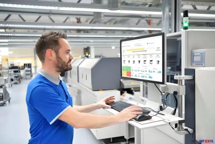
- Good for automation and higher yield. SMT is easy to automate. That raises production efficiency and product yield.
- Lower material cost. Most SMT parts already cost less to package than similar THT parts. As a result, sale prices for SMT parts can be lower than THT parts.
- Simplify product assembly and lower production cost. SMT reduces assembly steps. The overall processing cost for functional circuits is lower than through-hole. Total production cost can drop by 30%–50% in many cases.
Advantages of THT
Although SMT and THT both matter for board quality, neither method is always best. When used properly, they can complement each other. In some PCBA assemblies, choosing THT over SMT has clear benefits. Here are some THT advantages.
- Good reliability. THT solder joints are full and strong. In drop tests and vibration tests, THT-mounted parts are less likely to fall off. In connector insertion and removal, THT soldered parts often hold up much better than SMT parts.
- Lower part cost for certain parts. For some components, THT (through-hole) parts cost less than SMD versions. For example, electrolytic capacitors in SMD packages are often much more expensive than through-hole electrolytic capacitors.
- Better for high-power discrete parts and heat sinks. For large power devices, THT mounting makes it easier to fit heat sinks and to increase the part’s thermal area. This solves heat dissipation better.
THT vs SMT — a real-world example
Take outdoor LED video walls that we often see in plazas, store fronts, and train stations. For outdoor LED screens, waterproofing is a major concern because of rain, snow, and other weather. Once water gets inside, short circuits can occur. That may burn the product or even cause fire. Using SMT makes it harder and much more costly to reach a reliable waterproof design. So outdoor LED screens rarely use SMT processing. Using THT, designers can make screens waterproof more easily and without too much extra cost. For large outdoor LED displays, THT will likely remain common for a long time. At least for things like outdoor LED walls, SMT will not fully replace THT in the next 50 years.
SMT and THT mixed process
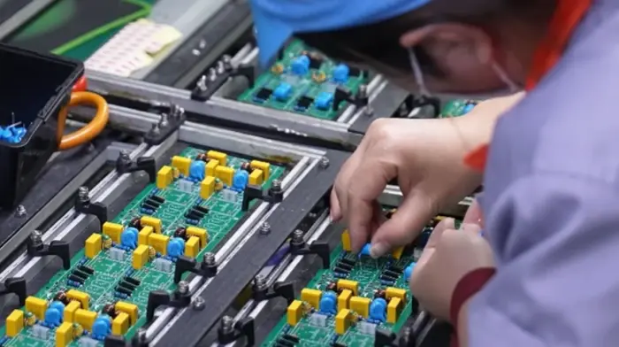
SMT can place small and thin parts precisely on the board. It is fully automatable and especially suitable for high-density, small-size PCBs. Production speed is high. THT uses drilled holes and wire leads to connect parts and the circuit. Wave soldering and manual soldering are common. THT is used more for large parts and parts that need high mechanical strength.
Some parts, like power inductors and large connectors, are hard to place as SMT. A mixed process combines the strengths of both methods. In production, SMT parts are placed and reflow soldered first. Then THT parts are inserted into the through-holes and soldered later. This retains SMT’s high precision and efficiency and keeps THT’s strong mechanical connection. It meets diverse manufacturing needs for many electronic products.
No single method is perfect. We must learn to take the strengths of both. Today, most PCBs use mixed SMT/THT assembly. However, SMT mixed production requires strict control of process parameters. If soldering parameters are wrong, they will not only affect the internal quality of joints but also cause defects like bridging, cold solder joints, or open joints. These defects seriously affect weld quality. In addition, PCB circuit design plays a key role.
Common solder defects to watch for in SMT mixed assembly
- Bridging. Too much solder or poor pad design causes solder to connect two adjacent pins. This makes a short circuit.
- Cold solder joints and poor wetting. If the reflow temperature or profile is wrong, the solder may not wet the parts well. This makes weak or intermittent connections.
- Tombstoning. Small passive parts can lift on one end during reflow, leaving one end un-soldered. This is often due to surface tension and uneven heating.
- Open joints. If solder does not reach the pad or lead, the joint will be open and the circuit will not work.
- Component shift. During reflow, parts can move from the correct position. Good stencil design and correct paste volume help avoid this.
Key points for successful SMT/THT mixed assembly
- Design the PCB with both SMT and THT in mind. Set clear keep-out areas, solder mask openings, and part placement rules. That reduces risk in later steps.
- Control solder paste printing and stencil design. Proper solder volume and pad design reduce bridging and tombstoning. Use correct aperture sizes on the stencil.
- Choose the right reflow profile. The profile must match the solder paste and the mix of components on the board. Too hot or too fast causes defects.
- Plan the assembly order. SMT parts are reflowed first. Then insert THT parts and solder them by wave or manual solder. This order minimizes heat damage and keeps parts secure.
- Use conformal coating or potting when needed. For outdoor or high-moisture products, use coating to improve waterproofing and reliability.
- Test and inspect. Use AOI (automated optical inspection), X-ray, and functional tests. These checks find defects early and improve yield.
Summary
SMT and THT each have clear strengths. SMT gives small size, higher density, better high-frequency performance, and good automation. THT gives strong mechanical joints, lower cost for some parts, and easier thermal solutions for high-power components. Most modern PCBs use a mix of both methods. The right choice depends on product needs, cost, and reliability targets. Good PCB design, tight process control, and the right assembly order are essential to get high yield and reliable products.