PCB to Chassis Grounding: Methods, Safety, and EMI Control
Many people are not sure whether the PCB should be grounded to the enclosure or not. When talking about grounding, some people think of using a single capacitor to "ground" the chassis. On Google you can find many articles and videos that suggest using a capacitor. Some even suggest a resistor in parallel with the capacitor. Why do they do this? Is this approach acceptable? This article explains the issue step by step.
Why connect the enclosure at all?
First, some electronic products use plastic housings and have two-prong power plugs.
Examples are electric cookers, some TVs, and desk lamps. These products belong to Class II
equipment. They do not rely on a protective earth (PE) connection for safety. Instead, they
use double insulation or reinforced insulation to prevent electric shock.

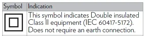
You can recognize these products by the double-square symbol. That symbol is an IEC standard symbol, found in IEC 60417-5172. It means the product uses double or reinforced insulation. In plain words, Class II equipment protects users by insulation alone and does not depend on grounding.
What is double insulation?
Double insulation means there are two layers of insulation. The first layer separates live parts from parts that cannot be touched. The second layer separates those untouchable parts from parts that people can touch. Because these products use double insulation, their enclosures are not grounded. That means there is no question of connecting the PCB ground to the enclosure ground in these cases.
Class I products
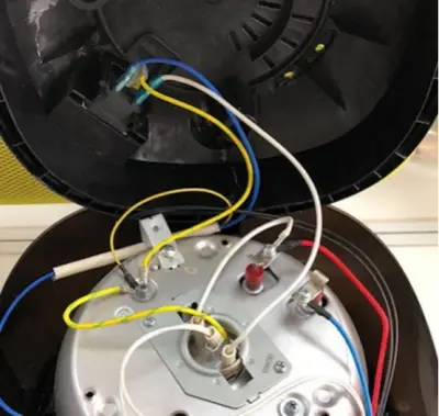
Class I products rely on enclosure grounding for safety. They use a three-pin plug with a protective earth (PE) contact. The metal case and any metal parts that can be touched are connected to the PE wire. For example, on a rice cooker the PE wire from the mains plugs straight to the metal inner shell and the heating plate. These parts can be touched. Grounding the enclosure is a mandatory safety measure for this kind of product. There is no negotiation about it.
Why connect PCB signal ground to chassis ground?
Some people think a metal enclosure acts like a Faraday cage and will shield internal circuits. If the metal shell were a perfect, fully sealed conductor and the internal circuits were completely floating, then outside electromagnetic noise would not reach the inside. But that is rarely the real case. Real metal enclosures have holes, seams, ventilation, and connectors. External electromagnetic waves can get in through those gaps and cause interference.
Also, a PCB needs power and external input/output lines. Power cords and I/O cables act as paths that bring interference into the enclosure. These cables couple interference into the internal circuits through parasitic capacitance. If the PCB ground is connected to the chassis, unwanted voltages on these parasitic paths can be shorted to chassis ground and removed from the circuit. That reduces interference.
However, a single-point ground between board and chassis can be ineffective at high frequency. The PCB ground cannot be at perfect 0 V everywhere at high frequency. Parasitic capacitances exist everywhere on the board. The practical solution for high-frequency situations is to use multiple grounding points.
For example, a computer motherboard carries many high-speed digital signals. It uses several mounting screws to connect the board ground to the metal case. Direct connections like this are common and very effective for reducing interference.
Where to place the single-point connection?
If a single direct connection is used, the choice of the connection point matters. After the PCB is fixed to the case, a ground loop can form. Common-mode interference current from the power cord may pass through the PCB ground and cause noise. To avoid this, place the chassis connection at the power entry point. In that way, any current on the PE conductor goes straight to the chassis and flows away, instead of going through the PCB ground.
Why use a capacitor to ground the enclosure?
You often see advice online that suggests using a capacitor between the PCB ground and the chassis. Many posts only say it is for noise or electrostatic discharge (ESD) without much detail. One common reason given is for passing ESD tests. If a capacitor is used, then there is no direct DC path between the PCB ground and the chassis. This can limit discharge current in some test setups. In that narrow sense, using a capacitor may help a product pass certain tests.
But this method is questionable in practice. ESD standards require discharge to the chassis and to exposed cable shields and connectors. The chassis, cables, and connectors should be properly grounded so the ESD does not reach the internal PCB. If the grounding of cables and connectors is poor, relying on a floating PCB with a capacitor to pass ESD is not the right fix. The cable and connector grounding must be designed properly. You should not use a floating board to compensate for bad grounding on cables.
A serious accident that changed my view
Real-World Consequence
This incident highlights the importance of proper grounding practices in electronic design.
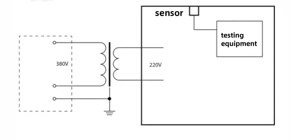
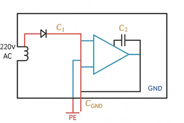
I once experienced a serious accident that made me stop trusting capacitor-to-chassis grounding. In that case, the insulation between the primary and secondary windings of a power transformer had aged and failed. As a result, mains voltage (220 V in my region) passed through the transformer and the rectified current reached the PCB.
The failure damaged the development board and the ST-Link debug adapter. More seriously, the fault current traveled along the USB cable into a connected PC and destroyed the PC’s motherboard. Transformer winding short is not a common failure, but it can and does happen. The hazard is serious.
If the PCB had been directly connected to the chassis, the leakage current would have gone to PE ground. The problem would likely have been contained to the enclosure and the PE system. The damage to external devices would have been much less and the personal risk would have been lower.
Ground loops and audio noise
Ground loops can cause problems too. Even though direct grounding is safer and generally better for EMI control, improperly placed grounding points can create loops that carry AC currents. These currents can cause noise. For example, audio systems often suffer from AC hum and noise caused by ground loops. Ground loops do not make the system safer, and they can worsen EMI.
The standard way to manage ground loops is careful grounding layout and routing. Single-point grounding is easy to describe, but hard to implement well. At mains frequencies and higher, currents can flow through parasitic capacitances and find unintended paths. That brings practical challenges. Engineers need to consider where currents will flow and how to keep sensitive circuits away from those paths.
Practical suggestions
Key Takeaways
Follow these recommendations for safe and effective PCB to enclosure connections.
- If the product is Class II and uses double insulation, do not connect the PCB ground to the enclosure. The design must comply with insulation rules and safety standards. The casing and internal structure must meet reinforced insulation requirements.
- If the product is Class I and has a PE connection, connect the enclosure to PE. Bond metal parts and accessible conductive parts to protective earth.
- For EMI control, connect the PCB ground to the chassis. Use multiple contact points for high-frequency return paths. Use mounting screws with conductive pads or metal standoffs that ensure good contact.
- Put the main chassis bonding point near the power entry. That way accessory currents go to the chassis and then to PE, not through the PCB ground and not through signal circuits.
- For ESD robustness, make sure the chassis, connectors, and cable shields are grounded properly. Design the product so ESD is handled at the enclosure and never injected into the PCB logic circuits.
- Beware of relying on capacitors or resistors to "isolate" the PCB from the chassis for safety. That might help some tests, but it does not protect against insulation breakdown or transformer faults.
- Expect that ground loops are possible. Minimize loop area for sensitive analog circuits like audio. Use star grounds or careful partitioning for audio and power sections when needed.
Summary
Whether you should connect the PCB ground to the chassis depends on the product class and safety rules. Class II products use double insulation and have no chassis ground. Class I products must bond the metal case to protective earth. For EMI reasons, chassis bonding of the PCB is usually helpful. Single-point grounding can work when used correctly, and the best place for the bonding point is near the power entry. Using just a capacitor to "ground" the chassis is not a reliable safety strategy. It may help with some ESD test setups, but it does not protect against real faults like transformer insulation failures. Good design practices, correct grounding of cables and connectors, and proper selection of insulation or protective earth are the correct ways to ensure safety and reduce interference.
Need a PCBA Quote?
Get professional pricing for your PCB assembly project. Our experts can handle complex designs with proper grounding and safety considerations.
Request PCBA QuoteFast turnaround quotes (within 24 hours)
Compliance with safety standards
Expert grounding recommendations