During the PCB lamination process, PP resin undergoes changes in states: "glass state →
high-elastic state → viscous flow state → high-elastic state → glass state". Due to
factors such as graphic design, flatness of the press steel plate, temperature
unevenness, and board arrangement, the resin flows irregularly in its molten state,
leading to uneven distribution of pressure on the board surface. When local pressure on
the board is insufficient, copper foil wrinkling defects occur.
This paper focuses on solving copper foil wrinkling by optimizing design, changing board
arrangement, and modifying lamination parameters to increase the pressure applied to
under-pressurized areas, particularly for wrinkling defects in structures with "thick
inner copper + thin PP sheet + thin outer copper foil". The paper explores the
mechanisms behind copper foil wrinkling in lamination and proposes a series of solutions
to significantly reduce the probability of wrinkling and improve the first-pass yield of
products.
Copper foil wrinkling after lamination appears on the surface of the copper foil and is
commonly striped, vein-like, or linear; in severe cases, it may form flaky wrinkles with
a depth of 0.05mm–0.5mm. The distribution typically corresponds to the pattern of the
subouter layer’s copper-free areas.
After wrinkling is detected, the outer layer circuit film and forming diagram must be
checked. If the wrinkles fall within the delivery unit, the wrinkled copper foil must be
stripped, and the lamination process must be repeated.
Theoretically, the pressure on the board * board area = hydraulic pressure * piston area
= input pressure * input area. That is:
Pressure per unit area on the board = Input pressure * (Board area / Input area).
Generally, if the average pressure per unit area on the board is 23 kgf, wrinkling will
not occur. However, for special types with extreme pressure distribution, the average
pressure per unit area may need to reach 30 kgf to avoid wrinkling.
This is because factors such as uneven board graphic distribution, press uniformity,
steel plate uniformity, and pressure transmission loss cause uneven pressure
distribution across the board surface. When local pressure is too low to shape the
resin, white spots, voids, or copper foil wrinkling will occur.
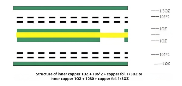
This is the most common type of wrinkling defect, accounting for more than half of all
cases. For example: inner copper 1OZ + 106*2 + copper foil 1/3OZ or inner copper 1OZ +
1080 + copper foil 1/3OZ structures.
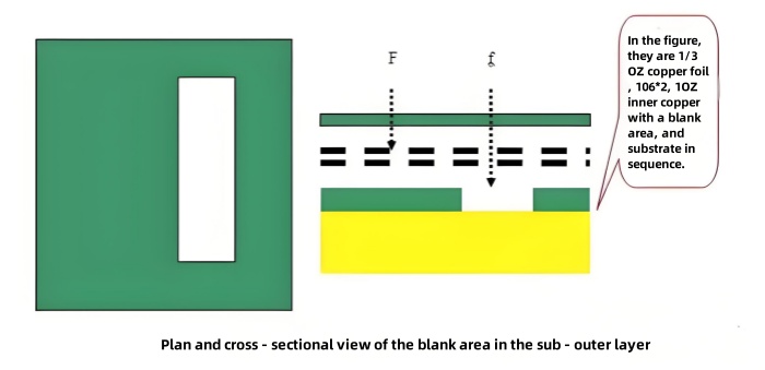
The pressure on the copper-free zones in the inner layer (f) is less than that on the
copper-containing zones (F), leading to uneven pressure distribution and easy wrinkling
in copper-free zones.
During hot pressing, the resin undergoes a state change: "solid → high-elastic → viscous
flow → high-elastic → solid". At a material temperature of approximately 80–140°C
(viscous flow state), the resin flows to fill the inner layer gaps. In this process,
less resin results in weaker filling ability; the softened PP sheet, as the best buffer
material, has weaker buffering ability when thinner. Therefore, the 106*2 PP structure
provides poor buffering and filling capabilities, offering little help in improving
wrinkling caused by uneven pressure distribution in copper-free zones.
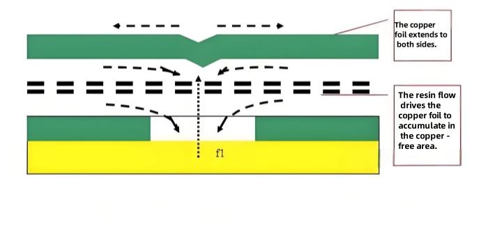
The viscosity of the resin in the viscous flow state remains above 3000 Pa·s, and its
flow to fill gaps can drive the copper foil to accumulate in copper-free zones.
Meanwhile, the buffering effect of resin softening and flowing increases the pressure
(f) and reaction force (f1) in copper-free zones, causing the copper foil to stretch
sideways under the action of f1. Before resin curing, if the expansion speed of the
copper foil is lower than the accumulation speed, wrinkling will occur.
ⅰ. Thinner copper foil has lower strength and is more easily driven by resin to
accumulate and fold in copper-free zones, which is why 1/3OZ copper foil is prone to
wrinkling.
ⅱ. Larger copper-free zones lead to more copper foil accumulation.
ⅲ. Pressure applied during resin flow is crucial for improving wrinkling. Premature
pressure application may cause other issues like uneven dielectric thickness, while
delayed application may result in low resin viscosity or curing, making even high
pressure equivalent to under-pressure and causing wrinkling. Generally, applying high
pressure when the material temperature in the middle layer of the opening is ~60°C and
the outer layer is ~90°C is reasonable.
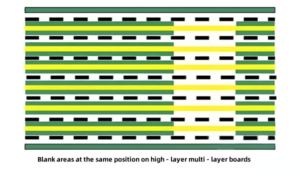
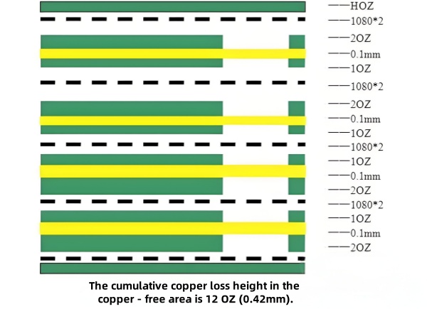
The stacked thickness of inner copper-free zones equals the total copper loss thickness
of each layer. In some high-layer boards, the total stacked copper loss thickness can be
as large as 0.5mm, meaning copper-free zones are 0.5mm lower than copper-containing
zones. During lamination, the pressure applied to these copper-free zones is far lower
than that to copper-containing zones, making wrinkling and lamination white spots
likely.
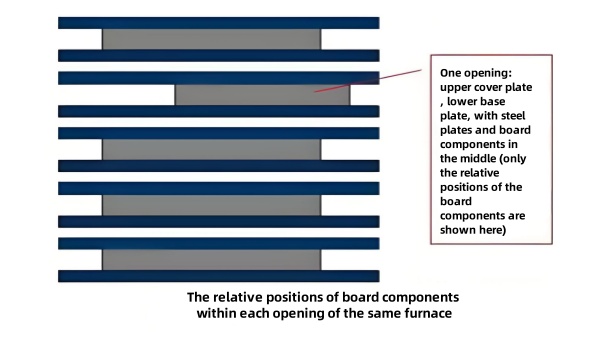
A batch of boards consists of multiple openings, each comprising an upper cover plate,
lower base plate, kraft paper, intermediate steel plates, and laminated boards, with
heat plates separating openings.
Generally, board alignment within the same opening should not exceed 10mm; otherwise,
sliding and pressure loss may occur. For different openings, due to the barrier of kraft
paper, cover/base plates, and heat plates, only the area of each opening is considered,
not the relative position of boards within openings.
In practice, mutual influence between openings is minimal, and wrinkling rarely occurs
due to poor alignment between different openings. However, in special cases—such as when
other openings in the same batch are well-aligned, but a poorly-aligned opening happens
to be a wrinkling-prone type described in 3.2.1—pressure loss in that opening may cause
wrinkling.
Using overly tall rivets or poor riveting quality can cause the rivets to lift the steel
plate during lamination, leading to white spots and wrinkling in areas near the rivets
due to insufficient pressure.
Non-compliant operations such as improper flattening of copper foil during board
arrangement, use of severely wrinkled copper foil, water on the steel plate surface, or
excessive kraft paper causing slow material temperature rise can all lead to wrinkling.
Since "local under-pressure" during hot pressing is the main cause of wrinkling,
countermeasures primarily aim to eliminate local under-pressure. Methods include
reducing pressure loss, increasing pressure in under-pressurized areas, optimizing
pressure application for higher efficiency, and using thicker copper foil with higher
strength.
-
Modify PP Thickness: Replace single-layer 1080 PP with 106*2 PP
to improve pressure distribution, ensuring compliance with design
specifications.
-
Optimize Pattern Design:
- Fill copper-free areas to reduce resin filling volume and enhance resin
buffering capacity.
- Adjust the position of copper-free areas to enable misaligned stacking
during lamination.
- Design slotted vents in enclosed inner-layer copper-free areas to facilitate
resin flow and pressure distribution.
-
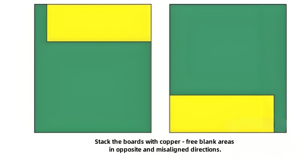
Misaligned Stacking: Arrange inner-layer copper-free areas in
opposite directions to minimize interlayer interference and pressure loss.
-
Insert Steel Plates: Place two steel plates every three layers
to enhance opening rigidity and reduce pressure loss.
-
Reduce Stacking Layers: Decrease the number of boards per
opening to minimize pressure loss.
-
Add Buffer Materials: Insert aluminum sheets to improve uneven
pressure distribution.
-
Adjust Pressure Application:
- Advance high-pressure application by a few minutes.
- Lower preheating temperature or adjust the heating rate to ~1.5°C/min
(monitor for pressure point shifts).
-
Use Thicker Copper Foil: Replace HOZ with 1OZ copper foil for
lamination, then etch back to HOZ to enhance copper foil strength.
-
Increase Lamination Pressure/Area: Raise input pressure or
increase the stacking area to improve pressure allocation to under-pressurized
zones.
-
Modify PP Thickness: Replace single-layer 1080 PP with 106*2 PP
to improve pressure distribution.
-
Optimize Pattern Design:
- Fill copper-free areas to reduce resin volume and enhance buffering.
- Adjust copper-free area positions for misaligned stacking.
- Design slotted vents in enclosed inner layers.
-
Misaligned Stacking: Reduce interlayer interference by
staggering copper-free areas.
-
Insert Steel Plates: Enhance opening rigidity with steel plates
every three layers.
-
Reduce Stacking Layers: Minimize boards per opening to reduce
pressure loss.
-
Add Buffer Materials: Use aluminum sheets to balance pressure.
-
Adjust Pressure Application: Advance high-pressure timing,
lower preheating temperature, or adjust heating rate.
-
Use Thicker Copper Foil: Etch back after lamination to improve
strength.
-
Increase Lamination Pressure/Area: Boost pressure allocation to
critical zones.
Ensure boards are centered within steel plates and aligned across openings to minimize
pressure loss.
-
Water on Steel Plates:
1.1 Dry steel plates
immediately after cleaning.
1.2 Inspect and wipe steel
plates before use.
-
Severely Wrinkled Copper Foil:
2.1 Replace low-strength
1/3OZ copper foil with high-quality alternatives.
-
Mixed-Pressure Lamination of Boards with Different Areas:
3.1 Use matching plates
and insert steel plates between different board types to reduce interlayer
interference.
-
Excessive Kraft Paper Leading to Incorrect Pressure Timing:
4.1 Adhere to process
specifications for kraft paper quantity.
Relevant experiments were conducted on the analyzed measures. Based on the company’s
actual production and customer requirements, a 10-layer board with the same copper-free
zone position in all inner layers was selected (copper-free zone size: 10×80mm, with
outer layer circuits corresponding to the copper-free zones). In the first production
run, 100% of the boards exhibited wrinkling. The structure is shown in the figure.
Copper-free zones were stacked in opposite directions, and steel plates (without kraft
paper to avoid affecting material temperature) were inserted between layers to reduce
mutual influence. The stacking was reduced to 6 layers. Despite the inner copper-free
zone stacked thickness reaching 12OZ and thin outer copper foil, 36.4% wrinkling still
occurred after lamination.
With the company’s material temperature rise rate of ~1.5°C/min, normal lamination
parameters apply high pressure when the outer layer temperature reaches 86–90°C. In
repeat production, high pressure was applied at an outer layer temperature of 80°C and
inner layer temperature of 55°C (along with the above board arrangement measures).
Wrinkling defects were reduced to 13.6%.
Using supplementary boards and scrap inner layers for testing, the actual high pressure
on the board surface was increased from 26kgf to 30kgf based on previous measures. The
yield after lamination improved to 100%.
Misaligned board arrangement reduces mutual influence between upper and lower stacks, is
simple to operate, does not increase costs or affect production capacity, and is
suitable for improving copper foil wrinkling as well as all lamination products.
Inserting steel plates and reducing stacking affect production capacity but are highly
effective and reliable, with no risk of other defects even if ideal results are not
achieved, making them worthwhile for controlling copper foil wrinkling.
Early pressure application and increased pressure are the most effective for controlling
wrinkling but must be cautious about risks such as excessive resin flow and uneven board
thickness. The matching of pressure with temperature (pressure application timing and
temperature rise rate) requires multiple experiments to determine the optimal
combination for different materials, equipment, and product designs.
Improvement solutions for lamination copper foil wrinkling include optimizing design,
balancing board arrangement, and modifying lamination parameters, summarized as two key
points: "increasing pressure in local under-pressurized areas of the board" and
"improving pressure efficiency".
This paper analyzes various types of copper foil wrinkling in lamination and their
causes, proposes corresponding solutions, and verifies the effectiveness of these
measures through actual production. The solutions can be popularized to other boards and
provide a comprehensive approach to addressing various copper foil wrinkling issues.
 28 May 2025 17:19:03 GMT
PCBASAIL
 28 May 2025 17:19:03 GMT
PCBASAIL