Future of Automotive PCBs: Electrification & Smart Vehicles
 17 Jun 2025 15:21:19 GMT
PCBASAIL
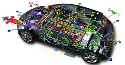
In recent years, concepts such as new energy vehicles and autonomous driving have captured widespread attention, and the traditional automotive industry is steadily evolving toward greater intelligence and electrification. As the adoption of new energy vehicles accelerates and autonomous driving technologies mature, the range of PCB-based applications in automobiles is expanding, thereby driving future growth in demand for automotive PCBs.
Applications of Automotive PCBs
In heavy-duty mining trucks like the Caterpillar 797F, PCBs underpin systems such as
electronic clutch pressure control, service interruption sensors, engine sensors, arc
switches, secondary interruption controls, axle speed sensor circuits, and position and
steering sensor circuits. Consumer vehicles also feature an impressive array of PCB-driven
subsystems: instrument clusters with LED or LCD displays; integrated GPS and radar
electronics; FM radio units; automatic door and locking systems; electronic relays for
controlling fuel valves and solenoids; timing circuits for engine control units (ECUs) or
engine control systems (ECS); automatic rear-view mirror controllers; airbag control
modules; front-, rear-, and side-mounted LED light control and driver circuits for
headlights, taillights, and turn indicators; as well as vehicle speed and acceleration
sensor and display circuits.

Modern automotive drive systems are entirely based on sophisticated PCBs running complex
electronic circuits in the background. These PCBs are preprogrammed to sense the vehicle’s
surroundings—typically via infrared and Doppler radar systems—to detect obstacles in close
proximity. Autonomous or “robot” drive systems use environmental inputs processed by onboard
PCB logic to manage braking, clutch engagement, steering, and throttle actuation.

Although all of these automotive PCBs are powered by the vehicle’s battery, in practice they draw from a largely maintenance‑free 12 V DC system. Wiring harnesses and fuses are installed throughout the vehicle to safeguard electronic modules against overcurrent or voltage surges.
Electric Vehicles
Today, media outlets and public discourse often reference the vision of a fully battery‑powered future automotive fleet, free of gasoline or diesel. Indeed, breakthroughs in battery technology have enabled new cells that can charge in a matter of hours and offer days of operation—akin to how smartphones back up our communications. Some electric vehicles (EVs) now provide multiple days of range on a single charge, while others can operate for weeks. None of these advancements would be possible without the underlying PCB architectures that route power from high‑capacity battery packs and manage the complex control electronics required for safe, efficient EV operation.
Types of Automotive PCBs
From the above overview, it is clear that automotive PCBs must offer top‑tier performance in
power handling, efficient heat dissipation, long operational life, and mechanical
robustness. When the vehicle’s dashboard or instrument panel is opened, one encounters
tightly packed electronics modules and wiring harnesses mounted on rigid PCBs—often
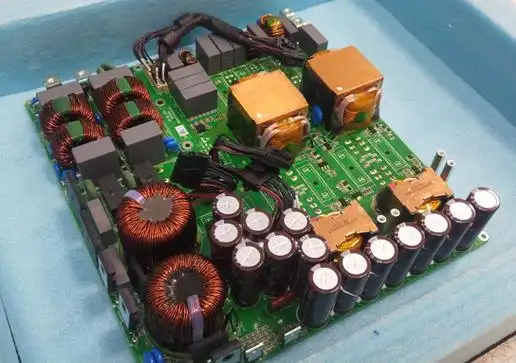
heavy‑copper, high‑density interconnect (HDI) boards—designed to carry substantial currents
from the main battery to auxiliary ceramic‑based substrates. These boards must withstand the
harsh environmental conditions encountered by vehicles operating in deserts, forests,
mountains, or under intense sunlight.

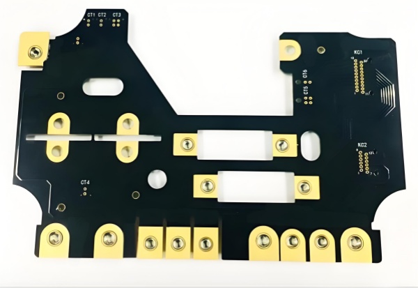
Metal‑core PCBs (MCPCBs) using aluminum substrates are ubiquitous in automotive LED lighting modules. High‑brightness LEDs draw substantial current and generate heat, necessitating an aluminum core beneath a copper power plane to serve as a thermal sink. Small actuators hidden within the vehicle body—controlling radiator fans, power windows, mirror motors, or other moving components—also draw significant current, making heavy‑copper MCPCBs essential to ensure minimal voltage drop and to prevent board warping or failure under thermal stress.
Flexible PCBs are employed behind instrument clusters to interconnect large LED or LCD displays to main processor boards, or to link various control modules via bendable flex circuits. Their lightweight, thin form factor allows them to conform to cramped spaces behind the dash. Rigid‑flex PCBs, which combine rigid and flexible layers, are increasingly used to optimize space and reduce connector count.
Power and Ground Routing in Automotive PCBs
Modern in‑car entertainment systems such as CD and VCD players incorporate large numbers of CMOS digital devices alongside mixed‑signal analog circuits. When these devices switch simultaneously, fluctuations in power rail voltage and ground potential can induce spikes, overshoot, or oscillatory ringing in signal waveforms.
A well‑designed power network minimizes voltage drop and noise generated by line impedance and high‑frequency electromagnetic coupling. Power traces should maintain consistent width rather than tapering mid‑span, and bends should use gentle arc shapes with obtuse angles greater than 90° to reduce impedance discontinuities. Vias should be generously sized, and wherever possible, bypass capacitors placed close to power vias to filter transient noise.
Ground planes play a dual role in enhancing EMC performance: by reducing loop area they lower
radiated emissions and improve immunity, and by providing low‑impedance return paths they
diminish crosstalk between adjacent circuits. The characteristic impedance of PCB traces
directly influences interference resilience; lowering common‑impedance coupling on ground
planes mitigates noise injection into ground loops.

Circuit boards should be subdivided by function, with each subcircuit’s ground returns connected in parallel to a single star‑point ground to prevent ground currents from one section flowing into another and causing crosstalk. In multi‑module boards, each module should have an independent ground loop that converges at a common ground tie‑point. Power and ground trace widths should be maximized; for components with 0.5 mm pin pitch, a minimum trace width of 0.3 mm (12 mil) is recommended.
On mixed‑signal boards, digital and analog grounds must be kept separate: failure to segregate them sharply increases EMC issues due to unfiltered digital switching noise coupling into sensitive analog circuits. Thus, digital and analog circuitry should be physically partitioned in both layout and routing.
Signal Routing Considerations
Automotive wiring bundles confine numerous signal and power lines—each with varying voltage, current, and direction—into a single harness, often alongside sensitive components improperly shielded or placed, generating EMI. Poor signal trace layout can exacerbate noise injection. Key guidelines include:
Maintain impedance uniformity: Avoid abrupt changes in trace width or layer transitions to prevent impedance discontinuities.
Minimize loop area: Keep signal‑return loops as small as possible to reduce radiation.
Orthogonal layer routing: In adjacent signal layers, route traces at right angles to each other to minimize capacitive coupling.
Layer assignment by signal type: Place high‑speed digital and low‑level analog signals adjacent to ground planes; assign low‑speed digital and high‑level analog signals to more distant layers.
Avoid parallel I/O routing: Input and output traces should not run in parallel to prevent feedback coupling.
Differential pairs for high‑speed signals: Use controlled‑impedance differential routing to reduce emissions and improve signal integrity.
Future Outlook for Automotive and PCB Industries
The dual trends of vehicle electrification and intelligence are driving significant growth in the automotive PCB market. Demand for high‑frequency, high‑speed PCBs is accelerating, with these advanced boards commanding greater technical barriers and market consolidation. As vehicles transition from traditional internal‑combustion drive systems to electric motors with battery and power‑control electronics, the proportion of electronic content rises dramatically. These factors are expanding the volume of PCBs used per vehicle, and as new energy vehicles scale in the market, automotive PCBs stand to benefit from even larger growth opportunities.
Increasingly complex electronic subsystems in new energy vehicles place stringent reliability requirements on PCBs. Beyond mere interconnection, automotive circuit boards must withstand harsh electrical, thermal, and mechanical stresses without failure modes that could compromise safety. Consequently, PCB manufacturers are continuously innovating advanced materials and fabrication techniques, competing vigorously for market share in a sector where long certification cycles and high barriers to entry ensure only the highest‑quality suppliers prevail.